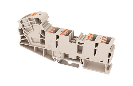

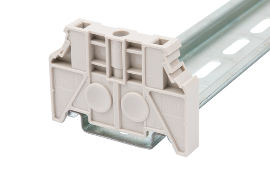
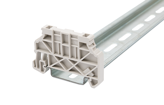
DPD16-P001
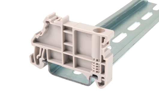
DIN-Schienen-AnschlussblöckeSteckverbindung
600V, 80A, Beige (default)
Zubehör Produktanfrageliste Hinzufügen
- Allgemeine Informationen
- Kurzbeschreibung
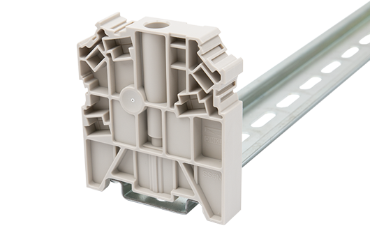
- Potential collective Terminal Block, Push-in Design
- Langebezeichnung
- Potential collective Terminal Block, Push-in Design, Width:15.30mm, 600V, 80A
- Kategorie
- Potential collective Terminal Block
- Farbe
- Beige (default)
- Anschlussart
- Push-in Design
- Verriegelungstyp
- Rail Mounting
- Länge (mm)
- 108
- Breite (mm)
- 15.3
- Höhe (mm)
- 51.5
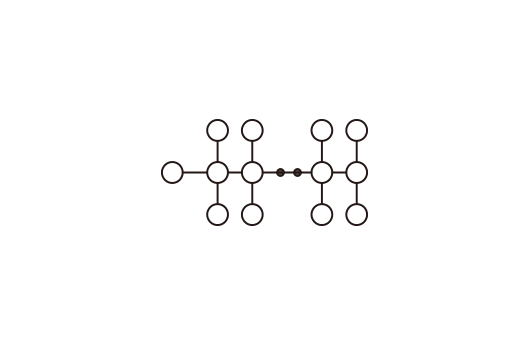
- Foto Anzahl der Pole
- ≧1P
- Level
- Single level
- Verbindungspunkte
- 13
- Materialinformation
- Verbindungsdaten nach IEC
- Verbindungsdaten nach UL
- Umwelt & Sicherheit
- UL Zulassungen
- CUL Zulassungen


-
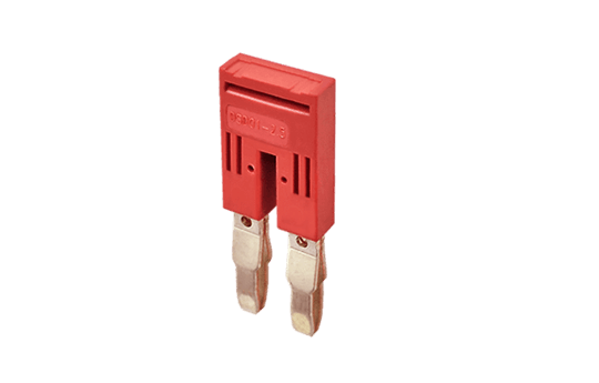
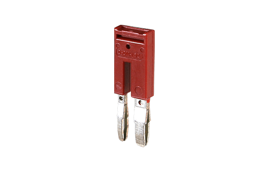
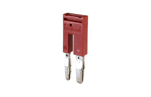
DSD01-2.5XXN
Plug-in bridge For DP2.5N Series, DPP2.5N Series, DP2.5N-3L Series, DP2.5SG Series, DPES2.5, DPES2.5-PE,
DKD10-P001, DPHD10-P001, DPD16-P001, DPD10-P001, DPH2.5 Series,
DPPES2.5, DPPES2.5-PE,
AK2.5 Series, AKK2.5, AKK2.5-D01, AKK2.5-D02, AKK2.5-D03, AKK2.5-D04, AKK2.5-PV
Red color.
Using UL94-V0 class of insulation material. - Add
-
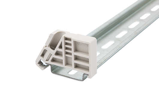
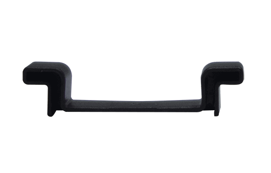
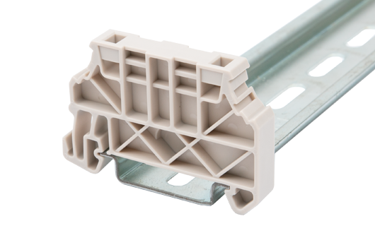
SS6N
End Bracket For TS-35, TS-35/15 rails.
Beige color.
Using UL94-V0 class of insulation material. - Add
-
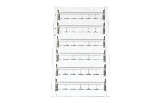
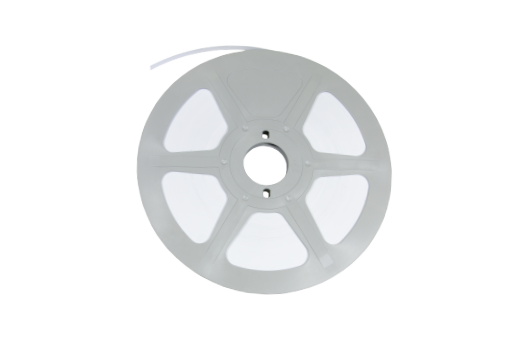
TM45LW
Marking Label For
BEST APPLICATION:
DP10, DP10-PE, DP10-TN, DP10-TN-PE, DKD10-P001, DPHD10-P001, DPH10 Series, AK10, AK10-PE, AK10-TN, AK10-TN-PE
AVAILABLE APPLICATION:
DP16, DP16-PE, DP16-TN, DP16-TN-PE, DPH16 Series, AK16, AK16-PE, AK16-TN, AK35, DPD10-P001, DPD16-P001, DK10-TF, DK10-TFA
White color.
Using UL94-V0 class of insulation material. - Add
-
SS11
End Bracket For TS-35, TS-35/15 rails.
Beige color.
Using UL94-V0 class of insulation material. - Add
-
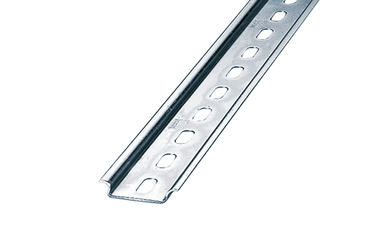
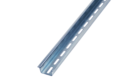
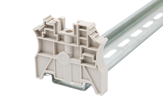
TS-35
DIN-Rail For DP / DK..N / DK.. / AK / DKB / DKU.. /DKM.. series.
Material is iron.
Length of 1000mm / 2000mm. - Add
-
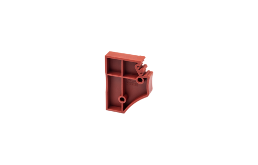
0208-E001
Spacer For DPH2.5 Series, DP2.5N Series, DPP2.5N Series, DPD10-P001, DKD10-P001, DPHD10-P001, DPD16-P001, DP2.5SG, DP2.5SG-L24*, DP2.5SGT, DP2.5SGT-L24*,
DP2.5SG, DP2.5SG-L24*, DP2.5SGR, DP2.5SGR-L24*, DP2.5SGRT, DP2.5SGRT-L24*, DPES2.5, DPPES2.5, DPES2.5-PE, DPPES2.5-PE, DP2.5N-T, AK2.5 Series
Red color.
Using UL94-V0 class of insulation material. - Add
-
TS-35/15
DIN-Rail For DK / DK-PE series.
Material is iron.
Length of 1000mm / 2000mm. - Add
-
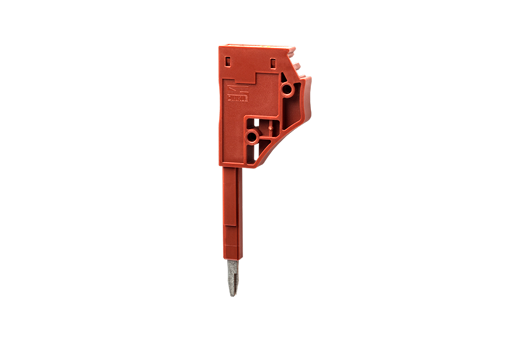
0208-T001
Test Plug For
DPH2.5 Series, DP2.5N Series, DPP2.5N Series, DPD10-P001, DKD10-P001, DPHD10-P001, DPD16-P001, DP2.5SG, DP2.5SG-L24*, DP2.5SGT, DP2.5SGT-L24*, DP2.5SG, DP2.5SG-L24*, DP2.5SGR, DP2.5SGR-L24*, DP2.5SGRT, DP2.5SGRT-L24*, DPES2.5, DPPES2.5, DPES2.5-PE, DPPES2.5-PE, DP2.5N-T, AK2.5 Series
Red color.
Using UL94-V0 class of insulation material. - Add
-
TS-35C
DIN rail end cap For TS-35 rail.
Black color.
Using UL94-V2 class of insulation material. - Add
-
TM-R100
Continuous Flat Marking Labels - Add
-
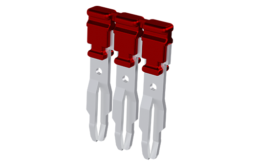
DSD03-1.5/2.5
Plug-in bridge For DP1.5N Series, DP2.5N Series, DPD10-P001, DPD16-P001, DKD10-P001, DPHD10-P001
Red color.
Using UL94-V0 class of insulation material. - Add
-
DSD06-2.5XXXT
Plug-in bridge For DP2.5N Series, DPP2.5N Series, DP2.5N-3L Series, DP2.5SG Series, DPES2.5 Series,
DPD10-P001, DKD10-P001, DPHD10-P001, DPD16-P001, DPH2.5 Series,
AK2.5 Series, AKK2.5 Series, DPPES2.5, DK2.5L-3L
Red color.
Using UL94-V0 class of insulation material. - Add
-
SS7N
End Bracket For TS-35, TS-35/15 rails.
Beige color.
Using UL94-V0 class of insulation material. - Add
-
SS4N
End Bracket For TS-35, TS-35/15 rails.
Beige color.
Using UL94-V0 class of insulation material. - Add
-
SS13
End Bracket For TS-35, TS-35/15 rails.
Beige color.
Using UL94-V0 class of insulation material. - Add
-
DSD03-2.5/6
Plug-in bridge For DP2.5N Series, DP6N Series, DKD35-P001, DKD35-P002, DPD10-P001, DPD16-P001, DKD10-P001, DPHD10-P001
Red color.
Using UL94-V0 class of insulation material. - Add
-
SS5N
End Bracket For TS-35, TS-35/15 rails.
Beige color.
Using UL94-V0 class of insulation material. - Add
-
SS2N
End Bracket For TS-35, TS-35/15 rails.
Beige color.
Using UL94-V0 class of insulation material. - Add
The web catalog is for reference only. Dinkle remains the right of product modification and engineering change of the design. The final product is made according to engineering drawing.
