
General information
Material information
Connection data-IEC
Connection data-UL
Environment & Safety
UL Recognized
CUL Recognized
-
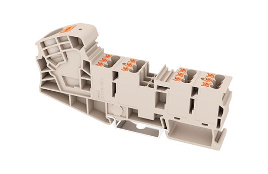
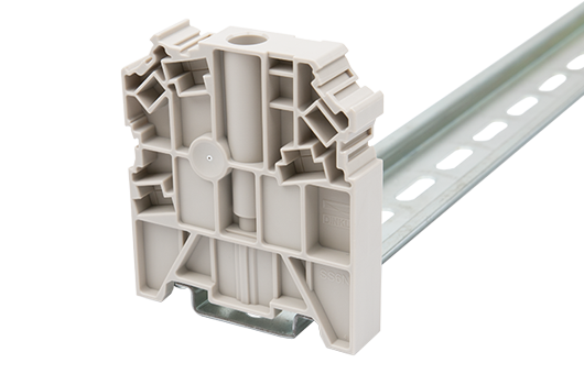
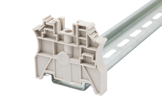
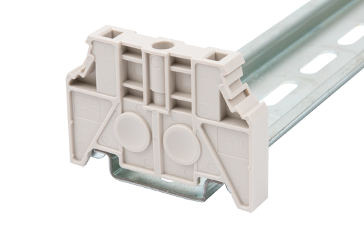
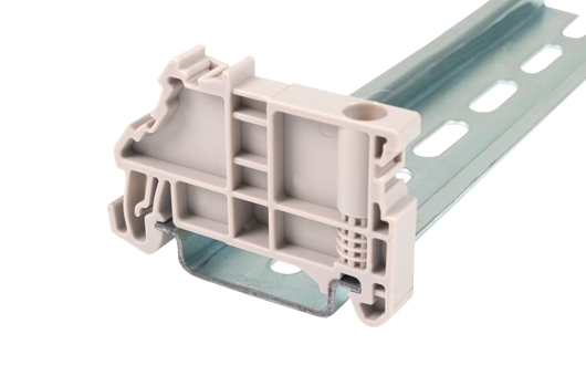
General information
- Short description
- Potential collective Terminal Block, Push-in Design
- Long description
- Potential collective Terminal Block, Push-in Design, Width:15.30mm, 600V, 80A
- Category
- Potential collective Terminal Block
- Color
- Beige (default)
- Connection method
- Push-in Design
- Type of locking
- Rail Mounting
- Length (mm)
- 108
- Width (mm)
- 15.3
- Height (mm)
- 51.5
- Number of positions
- ≧1P
- Level
- Single level
- Connection points
- 13
-
Material information
- Insulation material
- PA
- Insulation material group
- I
- Flame retardant rating , compliant with UL94
- V0
- Insulation resistance
- ≥500MΩ at DC 500V
-
Connection data-IEC
- Rated voltage (V)
- 1000
- Rated current (A)
- Line Side: 76 / Load Side: 24
- Rated voltage (III/3)(V)
- 1000
- Rated impulse voltage (III/3)(KV)
- Line Side: 8 / Load Side: 6
- Conductor cross section solid. min (mm²)
- Line Side: 0.5 / Load Side: 0.14
- Conductor cross section solid.max (mm²)
- Line Side: 25 / Load Side: 4
- Conductor cross section stranded. min (mm²)
- Line Side: 0.5 / Load Side: 0.14
- Conductor cross section stranded. max (mm²)
- Line Side: 16 / Load Side: 2.5
- Conductor cross section flexible, with min ferrule without plastic sleeve (mm²)
- Line Side: 0.5 / Load Side: 0.25
- Conductor cross section flexible, with max ferrule without plastic sleeve (mm²)
- Line Side: 16 / Load Side: 2.5
- Conductor cross section flexible, with min ferrule with plastic sleeve (mm²)
- Line Side: 0.5 / Load Side: 0.25
- Conductor cross section flexible, with max ferrule with plastic sleeve (mm²)
- Line Side: 16 / Load Side: 2.5
- 2 conductors with same cross section flexible, min twin ferrules with plastic sleeve (mm²)
- Line Side: 1.5 / Load Side: 0.5
- 2 conductors with same cross section flexible, max twin ferrules with plastic sleeve (mm²)
- Line Side: 4 / Load Side: 0.5
- Slotted screwdriver size (Blade thickness x Width)(mm)
- 0.6x3.5 & 1x5.5
- Stripping Length (mm)
- Line Side: 17~18/ Load Side: 9~10
- Mounting rail
- TS-35
- End cover plate required
- NO
- Grounding connections
- NO
-
Connection data-UL
- Rated voltage (UL/CUL Group B)(V)
- 600
- Rated current (UL/CUL Group B)(A)
- 80(Line) 20(Load)
- Rated voltage (UL/CUL Group C)(V)
- 600
- Rated current (UL/CUL Group C)(A)
- 80(Line) 20(Load)
- Rated voltage (UL/CUL Group D)(V)
- 600
- Rated current (UL/CUL Group D)(A)
- 5
- Min. solid wire connection (AWG) acc. to UL/CUL
- Line Side: 20 / Load Side: 26
- Max. solid wire connection AWG acc. to UL/CUL
- Line Side: 4 / Load Side: 12
- Min. stranded wire connection AWG acc. to UL/CUL
- Line Side: 20 / Load Side: 26
- Max. stranded wire connection AWG acc. to UL/CUL
- Line Side: 4 / Load Side: 12
-
Environment & Safety
- Back of the hand protection (YES or NO)
- YES
- Finger protection (YES or NO)
- YES
- Operating temperature. max (°C)
- 120
- Operating temperature. min (°C)
- -40
-
UL Recognized
- Wire Range (Group B)(AWG)
- Line Side:20~4 / Load Side: 26~12
- Rated voltage (Group B)(V)
- 600
- Rated current (Group B)(A)
- Line Side:80 / Load Side: 20
- Wire Range (Group C)(AWG)
- Line Side:20~4 / Load Side: 26~12
- Rated voltage (Group C)(V)
- 600
- Rated current (Group C)(A)
- Line Side:80 / Load Side: 20
-
CUL Recognized
- Wire Range (Group B)(AWG)
- Line Side:20~4 / Load Side: 26~12
- Rated voltage (Group B)(V)
- 600
- Rated current (Group B)(A)
- Line Side:80 / Load Side: 20
- Wire Range (Group C)(AWG)
- Line Side:20~4 / Load Side: 26~12
- Rated voltage (Group C)(V)
- 600
- Rated current (Group C)(A)
- Line Side:80 / Load Side: 20


-
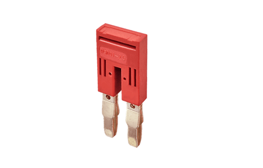
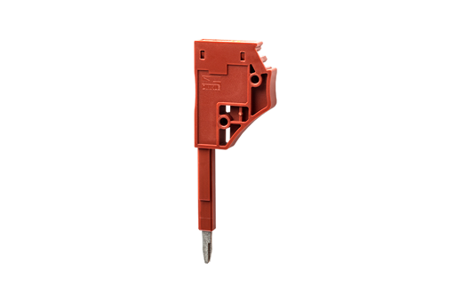
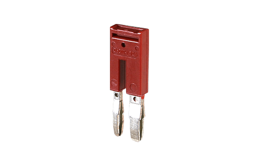
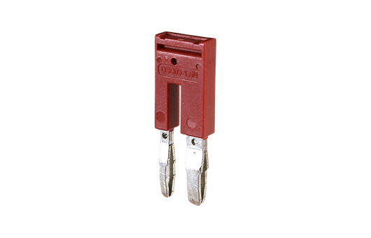
DSD01-2.5XXN
Plug-in bridge For DP2.5N Series, DPP2.5N Series, DP2.5N-3L Series, DP2.5SG Series, DPES2.5, DPES2.5-PE,
DKD10-P001, DPHD10-P001, DPD16-P001, DPD10-P001, DPH2.5 Series,
DPPES2.5, DPPES2.5-PE,
AK2.5 Series, AKK2.5, AKK2.5-D01, AKK2.5-D02, AKK2.5-D03, AKK2.5-D04, AKK2.5-PV
Red color.
Using UL94-V0 class of insulation material. - Add
-
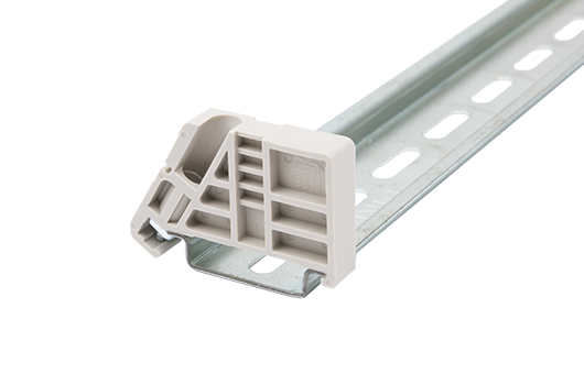
SS6N
End Bracket For TS-35, TS-35/15 rails.
Beige color.
Using UL94-V0 class of insulation material. - Add
-
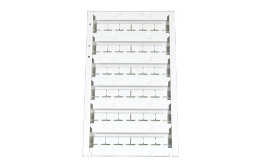
TM45LW
Marking Label For
BEST APPLICATION:
DP10, DP10-PE, DP10-TN, DP10-TN-PE, DKD10-P001, DPHD10-P001, DPH10 Series, AK10, AK10-PE, AK10-TN, AK10-TN-PE
AVAILABLE APPLICATION:
DP16, DP16-PE, DP16-TN, DP16-TN-PE, DPH16 Series, AK16, AK16-PE, AK16-TN, AK35, DPD10-P001, DPD16-P001, DK10-TF, DK10-TFA
White color.
Using UL94-V0 class of insulation material. - Add
-
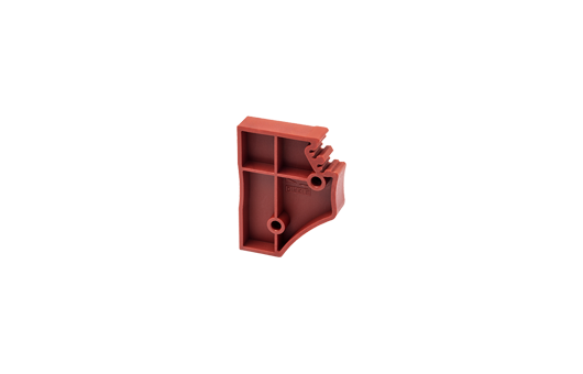
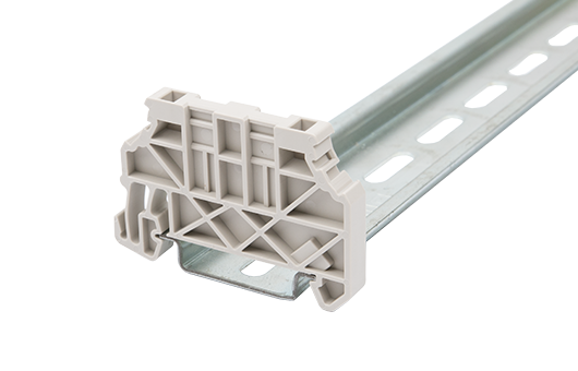
SS11
End Bracket For TS-35, TS-35/15 rails.
Beige color.
Using UL94-V0 class of insulation material. - Add
-
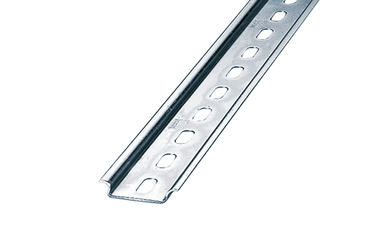
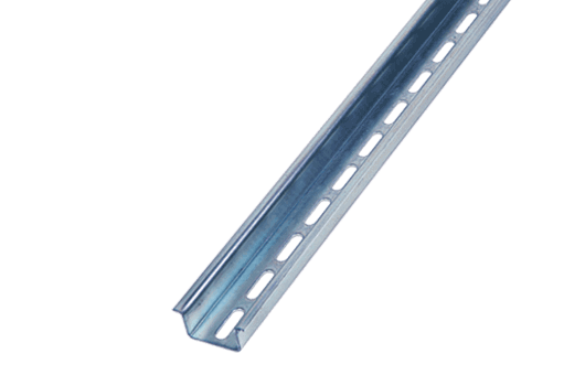
TS-35
DIN-Rail For DP / DK..N / DK.. / AK / DKB / DKU.. /DKM.. series.
Material is iron.
Length of 1000mm / 2000mm. - Add
-
0208-E001
Spacer For DPH2.5 Series, DP2.5N Series, DPP2.5N Series, DPD10-P001, DKD10-P001, DPHD10-P001, DPD16-P001, DP2.5SG, DP2.5SG-L24*, DP2.5SGT, DP2.5SGT-L24*,
DP2.5SG, DP2.5SG-L24*, DP2.5SGR, DP2.5SGR-L24*, DP2.5SGRT, DP2.5SGRT-L24*, DPES2.5, DPPES2.5, DPES2.5-PE, DPPES2.5-PE, DP2.5N-T, AK2.5 Series
Red color.
Using UL94-V0 class of insulation material. - Add
-
TS-35/15
DIN-Rail For DK / DK-PE series.
Material is iron.
Length of 1000mm / 2000mm. - Add
-
0208-T001
Test Plug For
DPH2.5 Series, DP2.5N Series, DPP2.5N Series, DPD10-P001, DKD10-P001, DPHD10-P001, DPD16-P001, DP2.5SG, DP2.5SG-L24*, DP2.5SGT, DP2.5SGT-L24*, DP2.5SG, DP2.5SG-L24*, DP2.5SGR, DP2.5SGR-L24*, DP2.5SGRT, DP2.5SGRT-L24*, DPES2.5, DPPES2.5, DPES2.5-PE, DPPES2.5-PE, DP2.5N-T, AK2.5 Series
Red color.
Using UL94-V0 class of insulation material. - Add
-
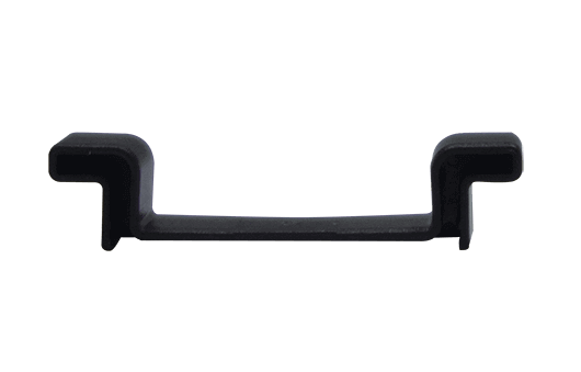
TS-35C
DIN rail end cap For TS-35 rail.
Black color.
Using UL94-V2 class of insulation material. - Add
-
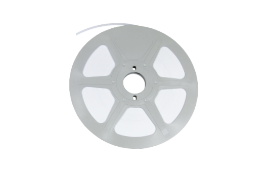
TM-R100
Continuous Flat Marking Labels - Add
-
DSD03-1.5/2.5
Plug-in bridge For DP1.5N Series, DP2.5N Series, DPD10-P001, DPD16-P001, DKD10-P001, DPHD10-P001
Red color.
Using UL94-V0 class of insulation material. - Add
-
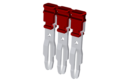
DSD06-2.5XXXT
Plug-in bridge For DP2.5N Series, DPP2.5N Series, DP2.5N-3L Series, DP2.5SG Series, DPES2.5 Series,
DPD10-P001, DKD10-P001, DPHD10-P001, DPD16-P001, DPH2.5 Series,
AK2.5 Series, AKK2.5 Series, DPPES2.5, DK2.5L-3L
Red color.
Using UL94-V0 class of insulation material. - Add
-
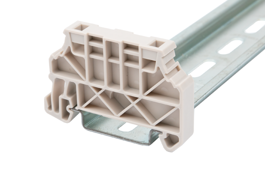
SS7N
End Bracket For TS-35, TS-35/15 rails.
Beige color.
Using UL94-V0 class of insulation material. - Add
-
SS4N
End Bracket For TS-35, TS-35/15 rails.
Beige color.
Using UL94-V0 class of insulation material. - Add
-
SS13
End Bracket For TS-35, TS-35/15 rails.
Beige color.
Using UL94-V0 class of insulation material. - Add
-
DSD03-2.5/6
Plug-in bridge For DP2.5N Series, DP6N Series, DKD35-P001, DKD35-P002, DPD10-P001, DPD16-P001, DKD10-P001, DPHD10-P001
Red color.
Using UL94-V0 class of insulation material. - Add
-
SS5N
End Bracket For TS-35, TS-35/15 rails.
Beige color.
Using UL94-V0 class of insulation material. - Add
-
SS2N
End Bracket For TS-35, TS-35/15 rails.
Beige color.
Using UL94-V0 class of insulation material. - Add
The web catalog is for reference only. Dinkle remains the right of product modification and engineering change of the design. The final product is made according to engineering drawing.